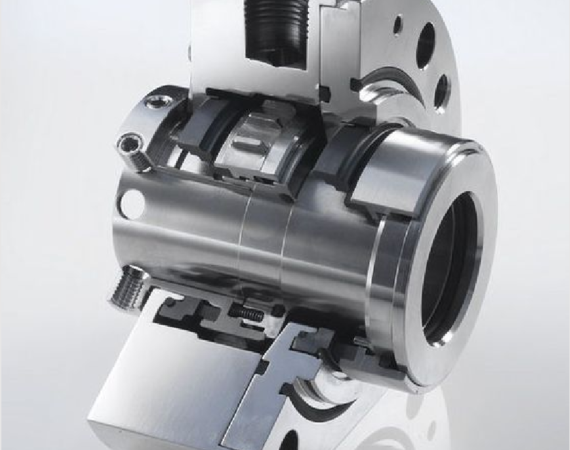
Category: Mechanical Seal Design Guide
Explore mechanical seal design basics, pump seal technology and piping plans. Start with the guides below, then prepare the operating data needed for seal selection.
Choose a mechanical seal design guide
• New to mechanical seals? Start with What is a mechanical seal? for an introduction before comparing designs.
• Reviewing a pump application? Read Pump mechanical seal technology as the next step in understanding pump sealing.
• Looking at the support system? Open the mechanical seal and piping plan guide to explore the relationship between the seal and its piping arrangement.
• Checking a discharge recirculation flush? Use the API Plan 11 guide for the flow path, restriction orifice, operating limitations and maintenance checks.
Prepare your seal selection data
A seal model or shaft diameter alone does not describe the full application. Before requesting a design review or replacement, gather the following information:
• Equipment and fit: pump manufacturer and model, existing seal reference, shaft or sleeve diameter, seal chamber dimensions, and available drawings.
• Operating conditions: fluid name and composition, normal and maximum temperature, seal chamber pressure, shaft speed, and start-up or shutdown conditions.
• Fluid behaviour: solids content, viscosity, corrosion concerns, and any tendency to crystallize, polymerize or vaporize.
• Seal support: current seal arrangement, piping plan, and available flushing, cooling or barrier-fluid supply.
• Reason for review: leakage location, service life, photographs of worn parts, and changes in operating conditions.
From the guide to your application
Use these articles to define the questions for your application review. Confirm dimensions, materials and operating limits against the equipment documentation before selecting a replacement. To discuss a specific pump, contact Fluid Tech Service with the information above. For other topics, visit the technical blog.
All articles in this category