
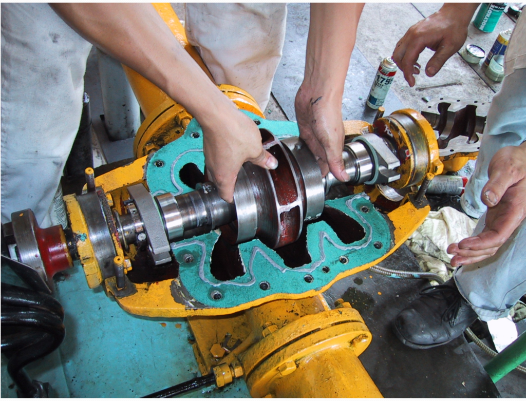
This checklist covers liquid-lubricated pump mechanical seals during scheduled maintenance or a leakage investigation. The installed seal drawing, pump manual and site isolation procedure govern the work. Gas seals and specialist reactor seals require their own instructions.
1. Preserve the failure evidence before cleaning
Record the pump tag, seal identification, process fluid, operating temperature and pressure, and time since the last repair. Note whether leakage began while stopped, at startup, after warm-up or after a process change. Photograph the assembled seal, pipe connections, deposits and both faces before washing away evidence.
- Isolate and lock out the equipment, verify zero pressure, drain safely and allow cooling before opening the chamber.
- Identify trapped-fluid hazards in the process and in flush, buffer or barrier circuits. Follow the site procedure for each circuit.
- Label rotating and stationary parts; keep each removed assembly together rather than mixing similar rings from different seals.
2. Inspect the seal and equipment together
Use a cleaning method compatible with the face materials and elastomers. Protect precision faces from scratches, abrasive debris and impact. Inspect faces for chips, scoring, uneven contact tracks, deposits and visible heat damage. Specialist flatness assessment is needed before deciding that a face can be reused; polishing by eye is not an acceptance test.
Check sleeve surfaces, O-ring grooves, gland seating surfaces, drive features and anti-rotation pins. Inspect springs or bellows for corrosion, distortion and blocked movement. Follow the model-specific replacement policy for secondary seals and springs. An old O-ring that looks intact may still be unsuitable for reuse.
Turn each observation into a next check
- Leakage while stopped: distinguish a gland or gasket leak from leakage across the faces; inspect static sealing interfaces and deposits that prevent movement.
- Scoring with trapped particles: investigate contamination and the flush circuit before selecting a different face material.
- Heat marks after startup: review priming, venting and support-fluid availability.
- Uneven contact tracks: check seating, shaft movement, bearings and alignment against the equipment instructions.
These are investigation prompts, not confirmed diagnoses. Keep observed damage separate from suspected causes in the work order.
3. Verify dimensions against the correct drawing
For every check, record the required value, measured value, measurement location and drawing revision. Confirm shaft or sleeve diameter, stationary seat dimensions, gland fit, working length, drive engagement and clearances. Measure runout and axial movement using the pump manufacturer’s method and the acceptance limits for the installed equipment and seal.
Free spring length is not the installed working length. Do not increase compression to compensate for leakage or infer face loading from an arbitrary difference between cover measurements. The seal design and prescribed assembly setting determine the correct position.
There is no single face-width allowance, ring clearance, runout limit or cooling-temperature trigger suitable for every seal. Resolve missing drawings and acceptance limits with the supplier before releasing the assembly.
4. Reassemble without introducing another fault
- Verify part identification and material compatibility with the process fluid and temperature.
- Use only the lubricant approved for the relevant secondary seal material and application. Lubricating an O-ring for fitting is a different instruction from coating precision faces.
- Keep sealing faces clean. Do not apply a general grease coating unless the specific seal instructions require it.
- Inspect shaft shoulders and grooves for burrs and protect elastomers during fitting.
- Tighten gland fasteners evenly to the specified torque and sequence; verify locating and anti-rotation engagement.
- For cartridge seals, follow the manufacturer’s sequence for securing the assembly and releasing setting devices. Confirm that devices are in their operating position before rotation.
Check permitted movement and free shaft rotation using the equipment procedure before restoring power. Correct assembly reduces failure risk but does not guarantee leak-free operation under every condition.
5. Check the complete support-fluid path before restart
Trace the actual support circuit rather than checking only the nearest valve. Confirm correct connections, serviceable filters and restrictions, and availability of the required cooling, venting and supply. Dual seals need their specified buffer or barrier arrangement and pressure relationship; all dual seals do not use the same setting.
Fill and vent a liquid-lubricated pump according to its manual before starting. Solids, crystallisation and hot service need measures selected for the actual process rather than a universal temperature threshold.
Illustrative comparison: similar leakage, different repair scope
Consider two pumps that leak soon after maintenance. One inspection finds a chipped stationary ring and a functioning flush circuit. The other finds deposits and an obstructed support line. The first job needs assessment of the damaged assembly; the second also needs correction of the support circuit. This is an explanatory example, not a reported customer case. Neither observation replaces a full investigation.
6. A maintenance record for the next shutdown
Use these fields in the work order so the next technician can compare evidence rather than repeat the same repair:
- Identity: pump tag, seal type, part number, drawing revision and fitted materials.
- Before removal: leakage location and timing, process conditions, support-system readings and photographs.
- Inspection: damage observed, measurement points, readings, acceptance references and replaced parts.
- Assembly: working-length setting, torque reference, lubricant identification and setting-device status.
- Restart: priming and venting checks, support readiness, leakage and temperature observations at site-defined observation points.
- Release: technician, reviewer, unresolved items and next inspection trigger.
Compare startup and stable-operation observations with manufacturer limits and the site’s baseline. Follow the shutdown procedure for excessive leakage, inadmissible temperature rise or another abnormal condition. Do not keep a pump running simply to see whether an unexplained leak disappears.
Maintenance questions
Should a mechanical seal be dismantled at a fixed interval?
Use the equipment maintenance plan, operating history and manufacturer guidance. Monitoring leakage and temperature can inform intervention; a calendar alone does not describe face or support-system condition.
Can a seal stored for a long time be installed immediately?
Check storage conditions, packaging, corrosion, elastomer condition and the manufacturer’s inspection requirements. Obtain assessment where identification or condition is uncertain.
What information helps a repair or replacement review?
Provide pump and seal identification, a drawing or measured dimensions, fluid and operating conditions, photographs before cleaning and failure timing. Include support-system information to review the seal in its operating context.
See our mechanical seal maintenance articles and installation guidance. For a component review, contact Fluid Tech Service with the maintenance record.
Technical references
Model-specific handling and maintenance examples are available in the John Crane Type 6 installation instructions and EagleBurgmann M3 operating manual. Their product-specific limits do not automatically apply to other seals.


